 Back in July I built RoboSketch which to this day still gets more traffic than any other post on my blog. People seem to love it. Somehow the spammers have figured this out because it gets dozens of comments daily hawking Acai Berry diets, Colon Cleansing products and my favorite which is a site that sells the book “How To Get Pregnant.” But the dirty little secret is that aside from the demo video, I was never able to get the RoboSketch to draw anything without failing in one way or another.
We’re not sending anyone to the moon here, so failure is always an option. In fact, failure isn’t feared, it’s desired. The best way to learn is hands-on, doing things and making mistakes. When you make a mistake yourself, that knowledge is ingrained in you in a concrete tangible way and you’re better off for it. So when my Etch A Sketch device was having conniptions, I took note of the failure and followed the advice of that most wise sage Tim Gunn. Make it work, people.
Adult Education
The first source of problems took a while to identify. It turns out that when you change directions on an Etch A Sketch – say you’re twisting the vertical knob clockwise and then you turn it counter-clockwise to back up – there’s slop in the mechanism. A lot of slop. You need to turn the knob in the new direction quite a ways before the pen starts moving in the new direction. So when I would tell the stepper motor to move from position 50 to position 100 and back to 50 I wouldn’t end up back where I started. For the longest time I thought this was a problem with my software or my motors.
Another issue was that the Etch A Sketch would shift around and sometimes pop out of alignment so the gears that meshed between the motors and the Etch A Sketch knobs would slip. And even when they didn’t completely slip, the shifting was enough to make the straight lines look very wobbly.
It turns out these are classic problems common to all machines of this type. The problems are so common that they’ve been given names. The slop when reversing direction is called backlash and the problem of keeping a part in place is called workholding. I learned this while taking a class in metal milling and recognized the concepts as the same ones I was encountering. If I had first heard about them in class, I suspect the information would not have stayed with me for very long. But having experienced these issues first-hand, I understood the discussion and the strategies to solve the problems.
Version 2
For the new version I wanted to get rid of slop wherever I could, so I designed it to be as rigid as possible. I also kept the mechanical linkages as simple as possible, so no more gears – the stepper motors would connect directly to the Etch A Sketch axles. This would require more powerful motors with enough torque to drive the axles directly. I purchased a pair of powerful 12V steppers from eBay for $1, and the AdaFruit Motor Shield allows your to use an external power supply to deliver >5V to the motors. I picked up some shaft couplers from Jameco to connect the motors to the Etch A Sketch axle shafts.


Rather than the flimsy single-layer acrylic enclosure I used before, I designed a stack of 6 sheets of acrylic to mount the motors. The result was solid and heavy and wouldn’t twist and warp as the motors turned like the old design.


The motors were mounted to the backmost sheet of white acrylic and then the red acrylic sheets were placed over the motors and the whole thing was bolted together to form a solid enclosure.


There was a dedicated space for the Arduino and Motor Shield board and the design had channels for routing the wires from the servos to the circuit board.

Say It Isn’t So
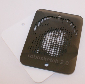
Functional though it may be, it was lacking something. When Tim Gunn says “Make it work” he’s looking for style and so we needed something to round out the aesthetics. Since the whole basis of the mechanism is Cartesian Coordinates, I grabbed a picture of Descartes, ran it through my Paper Pixels software and lasered it into some smoke-colored arylic badge for the front of the enclosure.

I was struck by two things after pulling the finished part out of the Epilog laser cutter. First, the resolution of the cuts is amazing. The thinnest pieces are half a millimeter in width, or about 2 hundredths of an inch. The second was that the picture bore a striking resemblance to the guy with the mustache in Hall and Oates. It’s not as obvious at full resolution but the resemblance is still there:

Finishing Touches
I affixed the badge and then attached the Etch A Sketch to the device using the shaft couplers. The final piece of the construction was a blue acrylic piece that held the Etch A Sketch tight to the motors so the couplers didn’t come apart at the rubber spider junction and also supported the whole mechanism so it stands upright.


The finished product not only works well, but looks great just sitting there on the desk.

The software running on the microcontroller is fairly simple. It implements a serial protocol that receives commands from the PC to move the pen and then keeps track of the pen position and implements a Bresenham line drawing algorithm to coordinate the two motors. The PC runs software that can read in SVG vector art files and then sends a stream of line segment commands to the RoboSketch. For bezier curves I subdivide the curves into line segments and send those so the Arduino doesn’t have to worry about anything more complex than a straight line.
The video below shows it drawing an SVG file with a vector drawing of a 3D surface. There’s nothing I can do about the backlash, so I do my best to account for it in software and the results are pretty accurate. The picture it’s drawing consists of 5,500 points and it gets through them all while keeping pretty solid registration.


