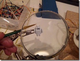
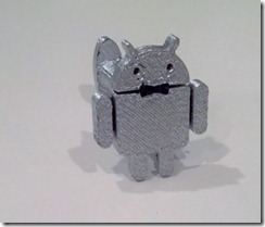
Lately I’ve been experimenting with how best to print more complicated designs on my Makerbot Replicator. The issues you usually run into are objects with overhangs – areas of plastic that don’t have anything underneath them to support them as they’re being extruded. My typical process has been to design something and then figure out some way to orient the object to minimize overhangs. But lately I’ve discovered some techniques that can easily allow you to print things with minimal support.
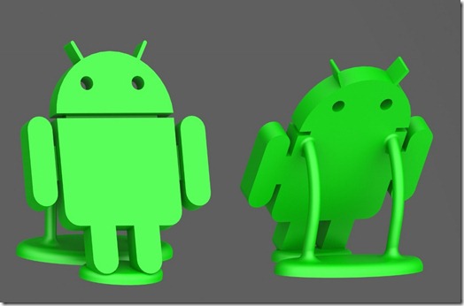
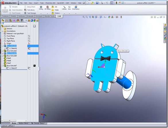
As an example, here’s a desk ornament I’m working on for a project. The picture below shows two views of the 3D model as designed. The first rule of thumb I applied here is for continuous surfaces to make sure anything that deviates from vertical creating an overhang does so at an angle of less than 45 degrees. The Android figure is designed at a 30 degree tilt which is sufficient to allow new layers to build upon older ones. Also, the support arms are curved to satisfy this constraint.
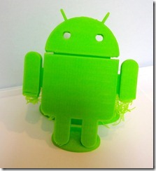
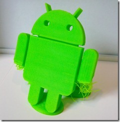
There are two sections of the design that are not well supported. If you didn’t notice them above, the next picture which shows my first attempt at printing shows the problematic areas well.
As the printer is building up layers, when it gets to the bottom of the body just above the legs it’s literally laying out a string of plastic in the air with nothing to support it. The same thing happens when it reaches the bottom of the arms. What happens is the string usually catches on something in the vicinity and after a few layers can end up providing just enough support for the layers above it. You can see that in the pictures above – there are about 10 layers of string but beyond that things worked fairly well.
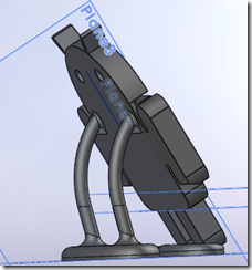
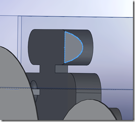
This made me think that perhaps adding just a little bit of support structure to hold those first layers (and that could be cut off later) would solve the issue. But looking at the arm, the very first layer is a tiny little little corner and might not be enough to build on. So first I sliced the bottom of the arm parallel to the ground by about 1/10th of an inch to expose some surface. The first picture shows the side view of the sliced arm and the second shows a view looking up at the arm from the ground. The blue selected outline is the first layer of plastic we’ll need to support.
So I designed some small rods and positioned them at the corners and apex of the blue profile curve so there would be something for them to attach to. Supporting the perimeter is usually enough, as the infill is made by zig-zagging back and forth which ends up sticking to the perimeter.
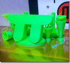
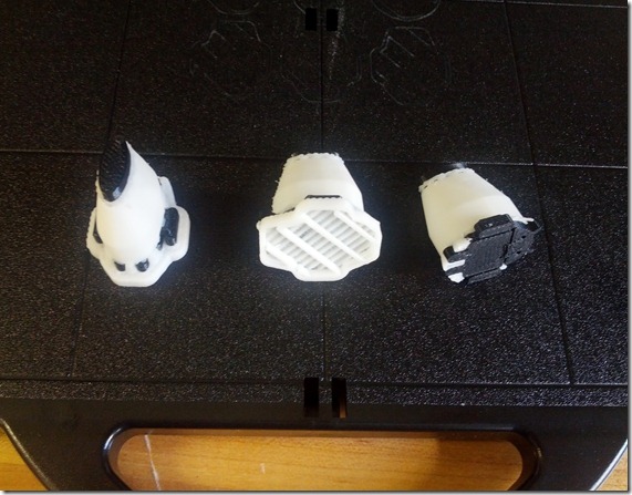
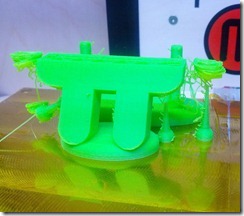 It turns out it was the correct strategy, but I failed several times in how I connected the support to the build platform. My theory was to make the supports tiny little pins so they would be easily broken off. But my first try the pins were so tiny they got knocked down or apart and didn’t last long enough to support the arm. The picture here shows the tiny pin supports on the right failing to support the arm layers. And the pins I had put on the left got knocked over during the print.
The second try is shown here. I made the supports small rods of 0.075 inches in diameter. This was enough to support the layers but also small enough to break off by hand. However, the bottom of the support base wasn’t large enough and didn’t stick reliably to the build platform. When printing with ABS anything with much mass needs a decent surface area to stick to the platform.
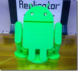
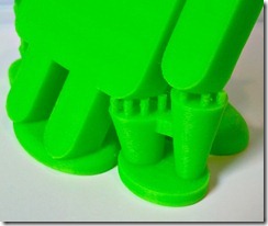
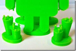
In my final attempt I made large ovals for the support bases and started the print. Three hours later the result was great. Below is a sequence of photos showing the result in the printer, then some details of the support structure. The final picture is after I snapped them off by hand, which required very little force.
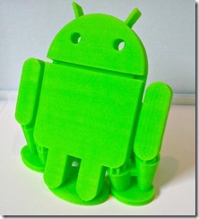
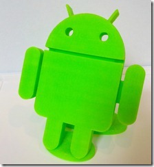
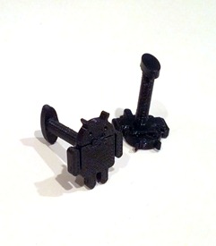
The final result after some light cleaning with a knife and sanding down some areas is shown below. It’s encouraging enough that I can see doing some more ambitious parts that I previously had thought were not printable with a Makerbot.
I published the 3D design files at Thingiverse so you can print your own. http://www.thingiverse.com/thing:32836
