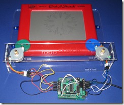
 I was at a local toy store recently and saw a display of Etch A Sketch toys. They were marketed as “retro” toys – something you would buy to remind you of a bygone era and feel thankful for having the great fortune to live in a more sophisticated period of history. I had an Etch A Sketch when I was a kid and I can assure you that when I played with it I did so without any cool ironic detachment. For me, that thing was bad-ass.
Keep in mind, this was before video games. I realize they’re putting Nintendo NES systems on key chains and giving them away in cereal boxes these days, but even NES was way beyond the first video games that came after my Etch A Sketch days. Atari 2600, Fairchild Channel-F, even Pong had yet to appear. But Etch A Sketch did exist and it’s true full name is the Etch A Sketch Magic Screen. It’s easy to overlook, but it’s designed to look like a TV. TVs used to have knobs on them – one for channel and the other for volume – just like the Etch A Sketch. So basically it was a TV that I could control and put any image I could imagine onto.
As long as that image was a rectangle, that is. Yes, in theory you can draw just about any image on an Etch A Sketch. It’s the same logic that states that just about any digital logic circuit can be built from only NAND gates or that just about any algorithm can be expressed in the form of a Turing tape machine. It’s possible to demonstrate these assertions mathematically, but they’re impossible in all practical terms. Unless you have some sort of monastic devotion you’d never accomplish it. Yes, there are the exceptions that prove the rule but at least in my case all the pictures were decidedly boxy.
I may lack in knob-twiddling ability, but I can build robots and write software. So I bought a magic screen with the plan of making some less-boxy pictures using technology. It’s been done before, in fact several times. But I wanted to give it a go myself.
We control the horizontal. We control the verical.
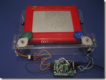
I had recently purchased a pair of 5V stepper motors and a motor driver shield from the fine folks at adafruit industries which seemed perfect for spinning the knobs. The question was how to connect the steppers to the knobs. As it happens I had also just bought a gear set from American Science & Surplus on a lark and they fit perfectly on the Etch A Sketch shafts and the stepper shafts. So I simply needed a way to line up the steppers over the knob gears.
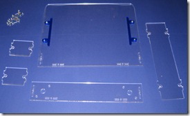
There are few problems you’ll encounter in life that can’t be resolved with the judicious application of a laser beam. I drew up a set of parts in Corel Draw and popped in to TechShop to cut them out of acrylic with their Epilog laser cutter.
I cut most of the parts out of clear acrylic except for the side guides which you can see in blue acrylic. The side guides hold the Etch A Sketch in place so it doesn’t move around laterally.
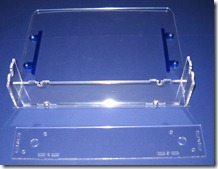
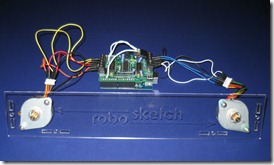
The parts screwed together and the stepper motors mounted on the top acrylic shelf. My 3AM measurements the night before were pretty accurate and when the whole thing was put together the gears meshed with the Etch A Sketch pretty well.
The irony of the fact that I’m essentially building toys to play with toys is not completely lost on me. There is a practical application of a sort here, as the goal is to produce some art that I can hang on the wall. For those wondering, I’ve gotten pre-approval from my wife so long as it’s in the basement.
A simple matter of typing
With the hardware done, all that’s left is some software to drive it. I have a friend at work named Eric who describes writing software as “typing.” That’s funny as hell, because it knocks software “engineering” down to the level of ditch-digging which is closer to the mark than folks who haven’t visited the sausage factory realize. I have a few ideas to experiment with to reproduce photographs on the robosketch, but only had enough time to do a bit of typing last night. So for the maiden voyage I ran a test with some simple vector art. I can’t quote the cartesian coordinates of many polygons off the top of my head, so I found myself typing in code to draw the only shape I could think of – a square, ironically.
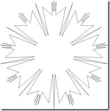
In an amazing stroke of luck, a few days later there was a cool post by the Evil Mad Scientist crew, (who appear to be lovely folks despite being both evil and mad) with a bunch of nice vector art. I grabbed one of their pictures and extracted the list of vector coordinates from it and fed them into my Arduino code that drives the steppers.
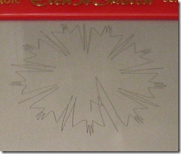
The results are passable for my first try. When the steppers change direction the acrylic tends to shift around which produces error in the first part of the new vector being drawn. This is what causes the corners to look rounded rather than sharp. Additional stabilization or just biting the bullet and directly attaching the steppers to the shafts will solve that.
The software also decided to go insane when it ran off the end of the vector table so there’s some bonus scribbles. It’s clearly a work in progress, but for those curious you can see the Arduino source code.
Here’s a video of the robosketch in action:
Tags: arduino, etch-a-sketch
VERY cool project!!!
Great project, I wanted to see how you connect the servo to the gears if that is posible, thanks.
You’ve done an excellent job. I will probably try something similar. I’ve noticed that you have some extra wires soldered on the motor shield from Adafruit Industries. What are they being used for?
Thanks,
John
Thanks, John. The extra wires are just hooked up to +5, GND and one of the free digital I/O ports on the Ardunio. I used it for a distance sensor for a different project and didn’t remove them. The other project was a cat toy that used servos to move a toy mouse around when it detected my cat. The cat figured tore it apart after about 2 minutes.
Carlos,
To answer your question on how I connected the servo to the gears, the answer is "poorly" as it turns out. The mechanism is very sensitive and the gears slip very easily. I’m going to have to redo this before I can get any decent amount of repeatability and precision.
Here are a few pictures showing what I did do. They show the small gear that I hot-glued onto the servo axle, the larger gear I hot-glued onto the Etch A Sketch axel and finally showing how they mesh. The servos get nice and hot after a while of use, which melts the glue and makes everything slip.
http://www.atomsandelectrons.com/make/pictures/IMG_0064.JPG
http://www.atomsandelectrons.com/make/pictures/IMG_0065.JPG
http://www.atomsandelectrons.com/make/pictures/IMG_0066.JPG
This would make one cool science fair project! Way to go and thanks for sharing.
very cool stuff, very intelligent to build a robot in this way.
hi i am half way through building one of these and am really struggling with the programming side of things i dont suppose you have the softwere and the aruduino code? great progect though
ben