 In the summer of 1980 my family took a trip to the East Coast, and we flew American Airlines. It was my first time on an airplane and I remember being very excited. I had good cause to be excited – I was about to have the entire course of my life impacted, but didn’t know it yet.
I was reading the in-flight magazine and came across something that boggled my young mind. It was a full-page advertisement for a computer – a personal computer that you could buy and use yourself. I must have sat there and stared at that page for 15 minutes studying the picture of this thing called a “personal computer”. I tore the ad out and carried it around with me for the rest of the trip. It took about a year of bugging my parents but they eventually bought me an Apple II with 16K of RAM.
These were my formative years and I learned that machine inside and out, making indelible memories that last to this day. I met Steve Wozniak at a book signing recently and told him I was surprised to find that nobody had yet grabbed the license plate “LDA C030” for their vehicle. [Blank stare from Woz] “You know, L..D..A..” I repeated myself more slowly and loudly, the way you might to someone who doesn’t speak Engligh in the hopes of being understood and with similar results. He had no idea what the hell I was talking about. And why should he? The obscure 6502 machine language command to make the Apple II speaker click would never have anywhere near the meaning to him as it did me. To me it was my fundamental introduction to making electronic music, whereas to him it was simply a feature he stuck in a product he built decades ago. His brain was doing the sensible thing and had purged this knowledge sometime in the past 30 years. In my case, this information was carved in stone and I put it all to use last weekend.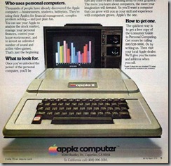
Actually the story begins another week or two earlier at the Silicon Valley Electronics Flea Market. I came across a guy with a bunch of Apple II computers stacked up and ended up buying an Apple //e and a disk drive for $20. His prices were $10 for an Apple //e and $25 for an Apple II+. The Apple II+ is technically the lesser machine – an earlier model that lacked the features of the Apple //e but is more expensive due to scarcity. The computer my parents purchased for me was the original Apple II, an even older and more rare model. I asked him if he had any of that model and he said no, but if he did they’d run a few hundred dollars.
I loved that he said this, because when the Apple //e was released I recall thinking that it was an abomination. My original Apple II computer came with a full set of schematics and programming documentation. The Apple //e was the first computer Apple released that didn’t include instructions on how to program it. By that time there was enough commercially available software and, like today’s computers, it actually did useful things without the owner having to program it. At the age of 15 this felt like a change for the worse and made the Apple //e a lesser computer in my mind.
I brought my $20 worth of computer gear home and decided to turn it on. The sound of the beep and the noise the disk drive made instantly transported me back 30 years – it was a sound as familiar as any I’ve heard in my entire life. It was the 1980s and I was a teenager with all the 6502 opcodes memorized. Time to build something.
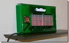
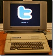
I have zero intention of becoming the Twitter Display Guy, but since I had just finished a Twitter Display project I thought it would be cool to do a Twitter/Apple II mash-up. So where to start…
Bootstrap
I had exactly zero software for the Apple //e I had just purchased, so I looked for a 6502 assembler that ran on the PC and was able to find several. But I needed a way to transfer the resulting binaries to the Apple and also would need a way to communicate with my PC to send the Twitter information.
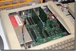
I ended up implementing an SPI-like interface between the PC and Apple II using an FTDI USB cable in bit-bang mode. This essentially gives you 4 logic lines you can control from your PC. I hooked these up to the Apple II joystick connector to the button inputs and wrote software on the Apple II to listen to the virtual button presses being hammered out by the PC. I tested this software first by just driving some LEDs with the FTDI cable to get the switching software right.
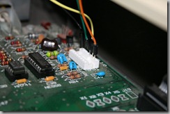
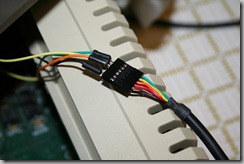
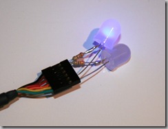 Once I could reliably toggle the logic lines on the FTDI cable, I hooked wires up to the Joystick button port as seen below. I call it the Track & Field protocol since it works by rapidly toggling the joystick buttons. Track & Field was an Apple II game where you had to mash the buttons as fast as you could to race, and was notorious for kids breaking their keyboards by pounding the buttons so hard. I was able to get this Rube Goldberg system working reliably at 3600 baud.
 But of course the very first piece of software had to be entered by hand on the Apple II, so I wrote a tiny bootloader in about 50 bytes that will load a stream of my bit-banged data into RAM. I then used this bootloader to transfer the full program. Writing the bootloader was surprisingly easy – I did almost all of it from memory. The 6502 has 8-bit registers but 16-bit memory addresses so you can’t reference a byte of memory indirect through a register. So you either need to store the address pointer in the first 256 bytes of memory (Zero Page) or use a longer instruction with an absolute address. I dimly recalled there were limitations on which Zero Page addresses were available for your use so I wrote the program to be self-modifying with absolute addressing.
 This loop increments the variable PagePointer to store each successive byte received. Look closely and you’ll see that PagePointer actually points to program code. It’s pointing to where the address byte is for the STA $xxxx,Y instruction. So the code is modifying itself as it goes through the loop. Computers go out of their way to prevent you from making these kinds of “mistakes” today but back then we all did it and it was bad-ass.
Not So Fast
The Apple II has an 8-bit 6502 CPU running at 1 MHz, so it can literally execute thousands of instructions per second. In other words, it’s about a million times slower that the computer you are using right now. So I wasn’t about to write a networking stack or Twitter client on the Apple II itself. Just like the TweetWall the communication with Twitter would happen on a PC and the Apple is just used for display.
The Apple II has 2 graphics modes. Low-resolution mode, or LORES as the cool kids call it, supports 40×40 pixels with 16 fixed colors. The colors are bizarre – lots of blues but kind of short on reds. Two of the colors are the exact same shade of gray, but are shifted a half pixel from each other. The other mode is high-resolution mode (HIRES) which gives 280×192 pixels and 6 colors. But you can’t just put any color anywhere you want. You kinda lose half your horizontal resolution once you start using color and even then you can’t just put a green pixel next to an orange one. It’s unbelievably complicated (cue Amiga fans to retort with tales of Hold And Modify mode). This same set of constraints is what makes the text on the Apple II have those purple and green fringes around the edges.
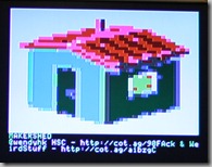
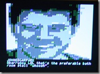
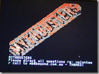
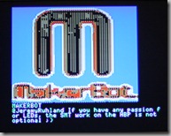
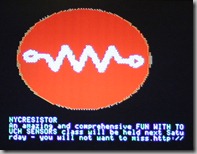
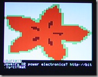
I wrote software on the PC to turn Twitter avatars into both LORES and HIRES graphic representations. The result is a cool 8-bit vibe, and in many cases the graphics are distant abstractions that bear little resemblance to the original image. Here are a few examples:
The PC software does the conversion of images into the exact native memory-mapped graphics format needed for the Apple II. Then it uses the bit-bang joystick protocol to pump the graphics buffers over directly to the screen. There is some additional software on the Apple II that can scroll the bottom text or the LORES graphics for transition effects.
Fragile
Once I got it working it was nice but I didn’t have a good way to save it. If I turned off the Apple //e I would have to re-enter the bootloader by hand and then re-download the software. I tried using the tape-recorder save/load interface but it wasn’t reliable.
I managed to win an auction on eBay for some blank 5.25” floppies and was able to download an image of the DOS 3.3 system disk for the Apple II. I used my bootloader to load this disk into memory the first time and once I had that going I was able to use it to initialize one of my blank eBay floppies and then I was golden. The video below shows the end result – a bootable Twitter floppy that shows old-school tweets. I recommend playing Rush while watching this.
