Following up on my flea market score earlier in the weekend I decided to assemble my treasures into something useful…or at least just into something period. By the end of Sunday night I was the proud owner of a 1-axis CNC plotter. It completely automates the process of drawing straight lines along a fixed axis :).
The eventual goal is to build a plotter/CNC that is actually useful, but you’ve got to start somewhere.
Design
I decided to go with a lead-screw drive because it seemed simpler than a belt drive and I had most of the parts on hand. The first thing I needed to do was figure out a way to attach a bolt to the carriage on the slide that could push it along as the lead-screw turned. I also needed a way to hold a pen on the carriage.
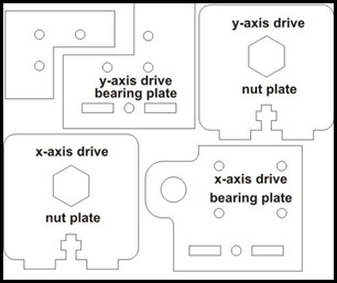 I had several sheets of 1/8” acrylic and access to a laser cutter at Techshop, so I drew up a set of parts in CorelDraw that would attach to the carriage and hold the captive nut and pen. I actually drew parts for both drive axes, but am only using the x-axis parts here. It was critical to line up the screw holes that attach the plate to the carriage, but all I had was my daughter’s plastic ruler from school to measure the dimensions. When I cut the parts I made sure to bring the slides with me and it turned out I was off by about 2mm on some of the holes so I had to re-do the cuts a few times.
I would have been totally lost on how to make a solid connection between the acrylic parts if I hadn’t read oomlout’s Instructable. I stole his templates for the connecting slots and it worked out brilliantly.
Fabrication & Assembly
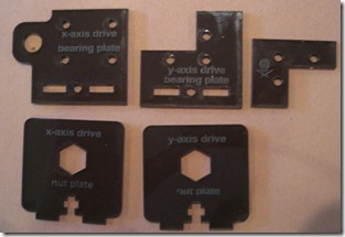
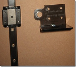
Below are the final acrylic pieces. It took about 3 minutes to cut them on a Epilog 45 watt cutter. The Epilog uses a print driver, so you essentially just “print” to it. A cool thing is you can combine cutting and etching in the same document – vector outlines will cut and bitmaps will do a raster scan etch. So I was able to label and cut the pieces with a single job. The picture on the right shows the 2 parts of the x-axis drive screwed together and ready to be attached to the carriage.
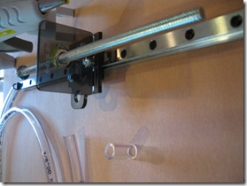
Finally I hot-glued the captive nut into the acrylic plate and threaded a long 1/4” bolt into it. The longest bolt I could find was 6” but the slide has almost double that in travel. I’ll get some threaded rod and cut it to size for the 2-axis version, but this was fine for testing. Then I attached the bolt to my stepper motor using a little bit of plastic tubing and hot glue.
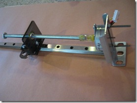
Testing
I wired the stepper up to an Arduino with one of the excellent Adafruit motor shields to drive it. The screw turned pretty easily, but I actually had no idea at all if the motor would have enough torque to make the thing work. The motor shield comes with a nice driver library, so it was only a few lines of code to get it working. Once fired up it worked well – the speed is about 1cm/s. I mounted the motor a bit high and my bolt isn’t quite straight which makes the spinning bolt a bit wobbly. If I fix those issues I can drive this at a higher speed.
For my first motorized project I’m declaring this a success. Riding this mechanism on top of a second axis movement and coordinating the steppers will be a bigger challenge, but now seems much more doable.