I’ve gotten quite a few questions regarding how to hook up and drive the Sure Electronics LED matrices I use in some of my projects, so here’s a quick brain dump on what you need to do.
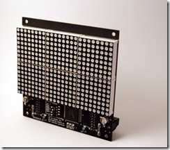
First off you’ll need to purchase some of the LED matrices. Sure Electronics has a storefront on eBay. There are 2 models of LED panel I’ve used: a 24×16 panel and a 32×8 panel. Prices are usually around $10-$12 each and depending on the day you check are available in various colors.
There are a variety of libraries that will drive these displays, so generally speaking you won’t need to know all the details on the interface protocol. But it’s useful to have the reference material available should you need it.
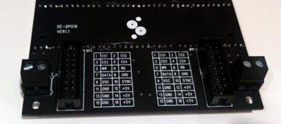
The Sure Electronics datasheet covers the cable pin connections and a high level overview of how to drive the display: http://www.sure-electronics.net/download/DE-DP017_Ver1.0_EN.pdf
Both of these displays use a Holtek HT1632 LED driver. The HT1632 datasheet goes into a bit more detail on how the chip works and the various modes, initialization procedure, etc.
Wiring Them Up
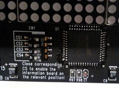
The displays come with a pair of ribbon cables which allows you to daisy-chain the displays together. So you only need the first display wired up to your microcontroller and the rest of them will chain off the first. Since they are all wired up to the same signals you need a way to identify the displays to address them from your code. This is handled with jumper switches on the front.
 The jumpers are labeled CS1 through CS4. Each display should have one and only one of these switches flipped to the On position to set its ID. If two displays have the same ID, they will act as clones of each other and the same image will appear on both.
The way I wire them up to my Arduino boards is as follows:
| Signal | LED Matrix Pin | Arduino Pin | Notes |
| +5V | 16 | 5V | Data sheet indicates this can pull 350mA of current max so make sure your regulator is up to the task. |
| GND | 15 | GND | |
| WR | 5 | Any Digital I/O | Write clock |
| Data | 7 | Any Digital I/O | Data to write |
| CS1..4 | 1..4 | Any Digital I/O | You’ll need to connect a CS pin to a discrete digital I/O pin for each display you are driving |
Software & Support
You’re spoiled for choice here – there are numerous libraries floating around.
There’s an epic thread on the Arduino forums covering how to interface to these displays. Among the 17 pages of posts are a variety of demos and sample libraries to use.
Adam Lloyd has a library that he maintains at http://github.com/devdsp/HT1632-AVR that supports reading from the display’s backbuffer as well as writing to it. If you do this you’ll need to wire up pin 6 on the matrix as well.
My library is available as well: SureLEDMatrix.zip and here’s a quick example on how to use it:
#include <SureLEDMatrix.h>
// —- PIN Constants ———————————-
int PIN_CHIPSELECT_1 = 5; // CS for LED matrix 1
int PIN_CHIPSELECT_2 = 6; // CS for LED matrix 2
int PIN_WRITE = 7;
int PIN_DATA = 8;
// Instance of LED matrices
SureLEDMatrix matrix1(PIN_CHIPSELECT_1, PIN_WRITE, PIN_DATA, kMatrixType_24x16);
SureLEDMatrix matrix2(PIN_CHIPSELECT_2, PIN_WRITE, PIN_DATA, kMatrixType_24x16);
int scroll = 0;
int maxscroll = 200;
void setup()
{
// Initialize I/O pins
pinMode(PIN_CHIPSELECT_1, OUTPUT);
pinMode(PIN_CHIPSELECT_2, OUTPUT);
pinMode(PIN_WRITE, OUTPUT);
pinMode(PIN_DATA, OUTPUT);
// Initialize the LED matrices
matrix1.Initialize();
matrix1.SetBrightness(2);
matrix2.Initialize();
matrix2.SetBrightness(2);
}
void loop()
{
// Draw the text on the right screen
matrix1.DrawText("Hello Cleveland!", 7, scroll, false);
// Draw the text on the left screen (24 pixels to the left)
matrix2.DrawText("Hello Cleveland!", 7, scroll-24, false);
// Scroll 1 pixel to the left
scroll = scroll-1;
if (scroll < -maxscroll)
{
scroll = 100;
}
}


Have you tried using the green display? The pixel mappings seem to be different from the red matrix
I have used both the red and green displays for the 32×8 matrices and have purchased (but not used) a yellow matrix. For the 24×16 size I’ve only ever seen them in red. In all cases the pixel addressing seems consistent.
However, I have run into trouble when I didn’t initialize the display controller properly. In the Initialize() code it sets up the controller and the initialization is different for the different matrix geometries.
hi!
I bought two of the green type, but it looks like only one work!
have you any idea in how to test if the chip is burned? broked? or is it only a bad soldering??
Hi
I am trying to use the above code and library to work with a 32×8 display but with no luck. The text seems to start from the middle of the display and is too fast to read. can some one help pls??
thanks
JP
Hi JP,
The text scrolling speed can be slowed down by adding a delay to the loop() funtion. At the very bottom of loop() before the closing brace add a line that reads:
delay(50);
This will delay 50 milliseconds or 1/20th of a second between steps of the scrolling animation. Make the delay bigger to slow it down more or a smaller delay to speed it up.
The issue with the text starting from the middle of the screen can be two things. First, if you’re using a 32×8 display and grabbed the library over a week ago there were some bugs related to interfacing to that display which would only use the left half of the display.
The other thing I can think of is that if you’ve modified the code to draw a long line of text, you will need to increase the value of "maxscroll" to be the width of the text in pixels. An approximate way to do it is to multiply the number of characters by 6 like this:
maxscroll = strlen("my message text that is really long") * 6;
Best of luck!
/y
I am very impressed with your library but I’m having difficulty using it with the new green led display. The characters flipped vertically in each of 6 square led modules. I know is a matter of a new addressing but cant for the life of me find where you have handled addressing in your code to correct it.
Any incites would be helpful.
Thanks
Karl
just to clarify its a new 24×16 green display. green matrix 2416 to be exact
I am very impressed with your library. I am however having some difficultly with using the library on the new 24×16 green led display. The text is vertically flipped in each of the 6 led matrices. I know that the addressing has changed and needs to be changes in your library I just cant for the life of me find where you handle the addressing.
A good picture of the change is here
http://timewitharduino.blogspot.com/2010/02/memory-mapping-in-16×24-led-displays.html
Any incites would be helpful.
Thanks
Karl
Karl,
That is truly insane. I had no idea the LEDs were mapped completely different in the green 24×16 display. I’d need to get one of them to verify this, but from your memory map in your blog I believe the following changes will work for you:
Somewhere near the top of SureLEDMatrix.cpp add a definition for this array:
// Given a 4-bit index, returns a 4-bit value with the bits reversed
unsigned char flipBits[16] = {0, 8, 4, 12, 2, 10, 6, 14, 1, 9, 5, 13, 3, 11, 7, 15};
Then, inside DrawText() search for the loop that starts with "while (charBytes- > 0)" and replace it with the following:
while (charBytes- > 0)
{
unsigned char charData = pgm_read_byte_near(pCharData);
unsigned char highNybble = flipBits[charData>>4];
unsigned char lowNybble = flipBits[charData & 0x0F];
#if RED_DISPLAY
// The existing code
this->WriteData(address, charData >> 4);
this->WriteData(address+1, charData & 0x0F);
#else
// Write the bytes in reverse order and flip the order of the bits
this->WriteData(address, lowNybble);
this->WriteData(address+1, highNybble);
#endif
address += stride;
++pCharData;
}
I’m just doing this from my head, so no guarantees but it should be something like that.
Good luck!
/y
Unfortunately that flips the letters across the x-axis or horizontally. The letters need to be flipped across the y-axis.
This is what is looks like with you code unaltered
http://yfrog.com/280602001252j
Its supposed to say 12345…..with the 5 slightly cutoff
Thanks
Karl
That memory mapping makes the text clipping and scrolling more complicated. I’ll have to pick up one of the green parts and play with it before I can update the library.
/y
Hi
thanks mate its working:):)
thanks again
JP
In case Karl and others are waiting, I did order a Green 24×16 from Sure’s eBay store. With any luck, it’s somewhere in the middle of the Pacific by now and I should have it shortly. When I get it I’ll fix up the pixel mapping.
By the way, isn’t that just like a hardware guy to have a completely different memory map for a green display than an identical red one. "They’ll just fix it in software" was uttered at some point.
/y
Hi
i have modified the program to my needs and it is working perfectly:)
the only prob is that i need a button that when pressed the screen clears.
i have tried to turn off every led but with no success. anyone have any idea pls??
thanks
JP