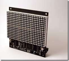
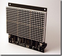
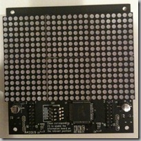
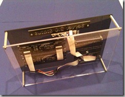
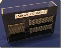
I’ve gotten quite a few questions regarding how to hook up and drive the Sure Electronics LED matrices I use in some of my projects, so here’s a quick brain dump on what you need to do.
First off you’ll need to purchase some of the LED matrices. Sure Electronics has a storefront on eBay. There are 2 models of LED panel I’ve used: a 24×16 panel and a 32×8 panel. Prices are usually around $10-$12 each and depending on the day you check are available in various colors.
There are a variety of libraries that will drive these displays, so generally speaking you won’t need to know all the details on the interface protocol. But it’s useful to have the reference material available should you need it.
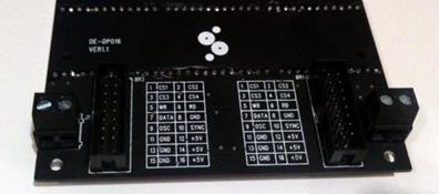
The Sure Electronics datasheet covers the cable pin connections and a high level overview of how to drive the display: http://www.sure-electronics.net/download/DE-DP017_Ver1.0_EN.pdf
Both of these displays use a Holtek HT1632 LED driver. The HT1632 datasheet goes into a bit more detail on how the chip works and the various modes, initialization procedure, etc.
Wiring Them Up
The displays come with a pair of ribbon cables which allows you to daisy-chain the displays together. So you only need the first display wired up to your microcontroller and the rest of them will chain off the first. Since they are all wired up to the same signals you need a way to identify the displays to address them from your code. This is handled with jumper switches on the front.
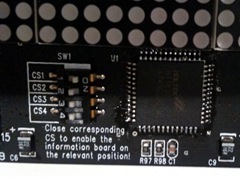 The jumpers are labeled CS1 through CS4. Each display should have one and only one of these switches flipped to the On position to set its ID. If two displays have the same ID, they will act as clones of each other and the same image will appear on both.
The way I wire them up to my Arduino boards is as follows:
| Signal | LED Matrix Pin | Arduino Pin | Notes |
| +5V | 16 | 5V | Data sheet indicates this can pull 350mA of current max so make sure your regulator is up to the task. |
| GND | 15 | GND | |
| WR | 5 | Any Digital I/O | Write clock |
| Data | 7 | Any Digital I/O | Data to write |
| CS1..4 | 1..4 | Any Digital I/O | You’ll need to connect a CS pin to a discrete digital I/O pin for each display you are driving |
Software & Support
You’re spoiled for choice here – there are numerous libraries floating around.
There’s an epic thread on the Arduino forums covering how to interface to these displays. Among the 17 pages of posts are a variety of demos and sample libraries to use.
Adam Lloyd has a library that he maintains at http://github.com/devdsp/HT1632-AVR that supports reading from the display’s backbuffer as well as writing to it. If you do this you’ll need to wire up pin 6 on the matrix as well.
My library is available as well: SureLEDMatrix.zip and here’s a quick example on how to use it:
#include <SureLEDMatrix.h>
// —- PIN Constants ———————————-
int PIN_CHIPSELECT_1 = 5; // CS for LED matrix 1
int PIN_CHIPSELECT_2 = 6; // CS for LED matrix 2
int PIN_WRITE = 7;
int PIN_DATA = 8;
// Instance of LED matrices
SureLEDMatrix matrix1(PIN_CHIPSELECT_1, PIN_WRITE, PIN_DATA, kMatrixType_24x16);
SureLEDMatrix matrix2(PIN_CHIPSELECT_2, PIN_WRITE, PIN_DATA, kMatrixType_24x16);
int scroll = 0;
int maxscroll = 200;
void setup()
{
// Initialize I/O pins
pinMode(PIN_CHIPSELECT_1, OUTPUT);
pinMode(PIN_CHIPSELECT_2, OUTPUT);
pinMode(PIN_WRITE, OUTPUT);
pinMode(PIN_DATA, OUTPUT);
// Initialize the LED matrices
matrix1.Initialize();
matrix1.SetBrightness(2);
matrix2.Initialize();
matrix2.SetBrightness(2);
}
void loop()
{
// Draw the text on the right screen
matrix1.DrawText("Hello Cleveland!", 7, scroll, false);
// Draw the text on the left screen (24 pixels to the left)
matrix2.DrawText("Hello Cleveland!", 7, scroll-24, false);
// Scroll 1 pixel to the left
scroll = scroll-1;
if (scroll < -maxscroll)
{
scroll = 100;
}
}
