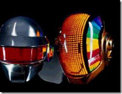
 I’m obsessed with LEDs. If I go to Halted to pick up 30 cents worth of capacitors, I will leave with 10 bucks worth of LEDs. When I first started learning about Arduino a few months back, most of my project ideas centered around LEDs. I imagined building my own Daft Punk helmet or a video wall made of LEDs.
That’s the best part of getting a new hobby – those first few weeks when everything is pure possibility and you have no idea how hard anything is. Maybe you recently decided to get into shape and have started exercising, so you read about Tabata Intervals or 20-rep squats and say to yourself “That sounds fun!” Naiveté like this tends not to last very long – doing anything that’s truly impressive requires hard work and this applies to LEDs just the same as it applies to squats.
The first roadblock in the way of my imagined LED projects was just how many of the damn things you need to do anything remotely interesting. Most of my ideas contemplate using LEDs as pixels, so to even draw a single character you need at least a 5×5 matrix or 25 LEDs. And of course you may as well multiply that by 3 because it’s gotta be RGB. But wait a minute…the Arduino microcontroller I’m using only has 12 discretely controlled digital outputs. How is this going to work exactly? After a bit more studying I’m up to speed on various types of multiplexing that push a lot of complexity into the software. You know, if I wanted to write a bunch of software to compensate for limited embedded hardware I could just drive in to work. It’s 8 reps into the 20-rep squat routine and reality is starting to set in.
That’s when I discovered macetech.com. They make specialized LEDs that are addressable and just generally full of awesomeness. The flagship is the ShiftBrite module which is a RGB LED that you can string together and control with a serial protocol that only requires a few pins. Its 10 bits of red, green and blue theoretically give you a gazillion potential colors. The smarts are in the LED, so the software stays simple – it’s the perfect solution. “But it’s expensive” I hear you cry. Yes, it costs more. If that’s an issue, I suggest you go back to scotch-taping your grandma’s hearing-aid batteries to 9 cent red LED throwies with the rest of the kids from your dorm. ShiftBrites are something entirely different – these things are practically sentient. To paraphrase Ferris Bueller, “I highly recommend them, if you have the means.”
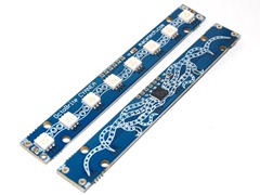
At Maker Faire this year, the macetech.com folks were showing off their newest product – the Octobrite. It’s sort of like 8 ShiftBrites stuck together on a board. Each is an individually addressable RGB LED controlled via a serial protocol, although the protocol is a bit different from the ShiftBrites. The compact form factor was perfect for a specific project I had in mind, which was an edge-lit picture etched into clear acrylic.
Etching The Picture
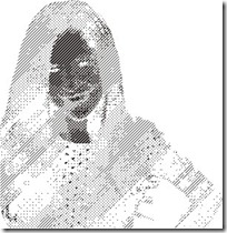 The idea is to illuminate a piece of clear acrylic from the edge and etch the acrylic so that the light reflects forward showing the image. I planned to use the Epilog Laser Cutter at Techshop to etch the image into the acrylic. Since the light entering from the LEDs is the same intensity for all areas of the image, we need some means of getting multiple gradations of brightness. I’ve previously described methods for turning photos into half-tone images and that’s what I did here as well. I took a photo and turned it into a monochrome bitmap using a 45-degree linear halftone.
One important difference in this case is that we want to etch the acrylic where we want light to shine. The laser cutter acts like a printer, and etches wherever there are dark pixels in the halftone image. So dark pixels in the image equates to light shining in the final product, which means I needed to invert the colors in the halftone which is why the picture looks spooky.
Doing anything with the laser cutter starts with finding the magic combination of speed, power and resolution that will give the best results with the material you’re etching. After a few test runs I found settings that gave me reasonable results.
Building The Hardware
I used an Ikea Ribba frame to house the picture. They come in a variety of sizes, but I really like the square ones as they are quite deep and allow you to mount your picture all the way back for a shadow-box like effect. Since I needed to squeeze in electronics, LEDs and a 3mm thick piece of acrylic this was useful.
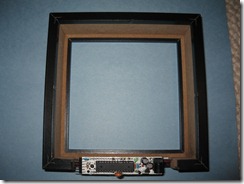
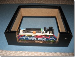
I used a Modern Device RBBB Arduino-compatible microcontroller board for this project, as it’s super-small and fit perfectly beneath the Octobrite in the frame. The Octobrite wants 3.3v for the LEDs but the RBBB had a 5v regulator so you can see I stuck a separate 3.3v regulator on there to power the LEDs.
I used a Dremel tool to cut out a space on the bottom of the frame to house the Octobrite. I hot-glued it into place so that it would be roughly in the middle of the frame. The Ribba frame comes with a spacer insert that I mounted the etched acrylic into with some more Dremel and hot-glue work. I was careful to make certain the exposed edge of the acrylic lined up directly over the LEDs.
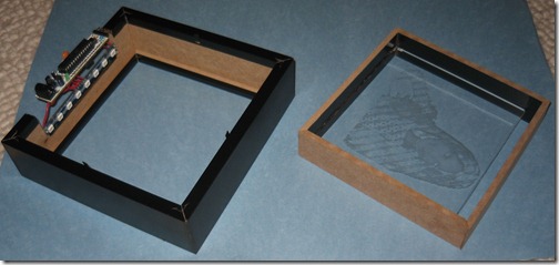
Through experimentation I discovered that the edge-lit acrylic is brighter on the smooth side, rather than the etched side. So I mounted the smooth side forward in the frame. Also, the light looks best contrasted against a dark background so I cut a piece of black construction paper and mounted it behind the acrylic. Putting everything together and closing up the frame was the last bit of the physical construction.
Software Light Show
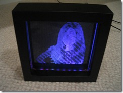 The final bit was to get the LEDs to do something interesting. The RBBB has a programming header exposed on it so I can update the software using my handy adafruit FTDI cable. As tempting as it was to do something complicated, I discovered that a few subtle fades through some colors looked the best.
They aren’t kidding about the “brite” part – I’m driving the LEDs at about 5% max current and it’s plenty bright. The board and voltage regulator stay nice and cool at this level and it gives enough light that the picture is clearly visible but not overwhelming.
I’ve published the Arduino source code for folks who’d like to adapt it for their use. You can edit the color table section near the top to modify the animation.
Here’s a video of the final result running. The lighting changes confused my video camera so the exposure isn’t quite right. It looks brighter and the animation is smoother in real life, but this gives an idea of how it came out.